Starting point: Chapters 1–7; physical concepts and approximations are introduced as needed.
Anchor example: A transmon coupled to a readout resonator.
This lesson includes explanations, worked examples, and problems with solutions. Advanced results whose proofs are outside the chapter are identified explicitly.
We now turn from general principles to devices. The first kind of device is built rather than found: an electrical circuit, cooled until it behaves as a quantum system. Its levels are designed instead of inherited from nature. Can such a circuit meet every requirement of a qubit?
We first quantize the simplest circuit, a capacitor and an inductor, and find an equally spaced ladder that is too regular to address. A Josephson junction adds a nonlinear energy, and in the transmon regime it makes the ladder slightly unequal. That small inequality sets both how a microwave pulse can control the qubit and how easily it leaks. Coupling two circuits then gives exchange and conditional phases. Coupling a circuit to a detuned resonator gives a readout, and counting wires, heat, and residual couplings shows what limits a large array.
Our first question is what quantum levels an electrical circuit has.
8.1 Circuit Qubits
A capacitor and an inductor exchange electric and magnetic energy, like a mass on a spring. Why can we not simply call their two lowest levels a qubit, and what element changes that? Quantizing the circuit gives an equally spaced ladder. A Josephson junction adds a nonlinear energy, and in the transmon regime that energy makes the ladder slightly unequal.
8.1.1 Oscillators and Josephson junctions
What does a capacitor connected to an inductor do? Let \(C\) be the capacitance and \(L\) the inductance. Let \(Q\) be the capacitor's charge and \(\Phi\) the flux, the time integral of the voltage across the inductor. Their stored energy is \(H=Q^2/(2C)+\Phi^2/(2L)\). The circuit equations \(\dot\Phi=Q/C\) and \(\dot Q=-\Phi/L\) give \(\ddot\Phi=-\Phi/(LC)\): an oscillator with angular frequency \(\omega=1/\sqrt{LC}\).
What are its quantum levels? We take one physical input: in the quantum description, \(\Phi\) and \(Q\) become Hermitian operators with \([\Phi,Q]=i\hbar\), the same rule that holds for a particle's position and momentum. Now define \(a\) through
Then \([\Phi,Q]=2i\Phi_{\rm zpf}Q_{\rm zpf}\), so the rule holds if \(\Phi_{\rm zpf}Q_{\rm zpf}=\hbar/2\). Choosing \(\Phi_{\rm zpf}=\sqrt{\hbar Z_c/2}\) and \(Q_{\rm zpf}=\sqrt{\hbar/(2Z_c)}\), with impedance \(Z_c=\sqrt{L/C}\), satisfies it. With this choice \(Q_{\rm zpf}^2/C=\Phi_{\rm zpf}^2/L=\hbar\omega/2\). Substituting into the energy, the terms with \(a^2\) and \((a^\dagger)^2\) cancel, and what remains is \(H=\hbar\omega(a^\dagger a+\tfrac12)\).
Why are the eigenvalues of \(a^\dagger a\) whole numbers? From \([a,a^\dagger]=1\) we get \([a^\dagger a,a]=-a\). So if \(a^\dagger a\ket\nu=\nu\ket\nu\), then \(a\ket\nu\) is an eigenvector with eigenvalue \(\nu-1\): \(a\) steps down by one. Its squared length is \(\bra\nu a^\dagger a\ket\nu=\nu\), which cannot be negative. Stepping down repeatedly would eventually produce a negative eigenvalue, unless the ladder ends at a state with \(a\ket0=0\). So \(\nu=0,1,2,\ldots\), and the energies are \(E_n=\hbar\omega(n+\tfrac12)\). The squared length also gives \(a\ket n=\sqrt n\ket{n-1}\). This is the lowering operator we used for an oscillating mediator, now derived for a circuit.
Equal spacing is exactly what prevents a resonant drive from singling out the lowest pair. Some element must make the energy nonlinear. That element needs a physical input of its own. In certain metals cooled to very low temperature, electrons bind into pairs that flow without resistance. This state is called superconductivity, and each pair carries charge \(2e\). A Josephson junction is a thin insulating barrier between two superconductors, through which pairs can tunnel.
Physical input (Josephson energy). The junction stores energy \(-E_J\cos\varphi\), where \(\varphi=2\pi\Phi/\Phi_0\) and \(\Phi_0=h/(2e)\) is the flux quantum.
Replacing the inductor's quadratic energy by this cosine makes successive transition frequencies differ, and that makes selective qubit control possible. The device must be cold for two reasons: superconductivity requires it, and the thermal excited population must be small.
8.1.2 The transmon regime
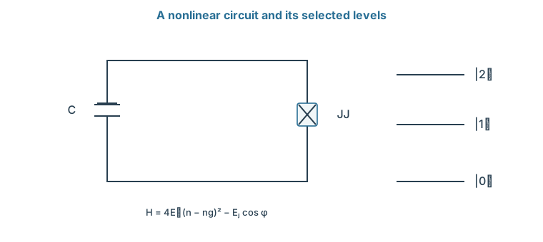
How unequal does the junction make the ladder? Count the charge in units of pairs: \(Q=2e(n-n_g)\), where \(n\) is the number of pairs that have tunnelled and \(n_g\) is an offset charge set by a gate voltage and by stray charges nearby. The charging energy becomes \(4E_C(n-n_g)^2\), with \(E_C=e^2/(2C)\). Together with the junction,
\[H=4E_C(n-n_g)^2-E_J\cos\varphi.\]
When \(E_J/E_C\) is large, \(\varphi\) stays near the bottom of the cosine, so we expand:
The quadratic part is an LC oscillator in disguise. Because \(\varphi=2e\Phi/\hbar\), the quantization rule becomes \([\varphi,n]=i\). Matching \(4E_Cn^2+E_J\varphi^2/2\) to the LC energy gives the level spacing \(\sqrt{8E_JE_C}\), and \(\varphi=\varphi_{\rm zpf}(a+a^\dagger)\) with \(\varphi_{\rm zpf}^2=\sqrt{2E_C/E_J}\).
What does the quartic term do to the levels? We quote the standard first-order result of perturbation theory. When a small term is added to a Hamiltonian with known levels, each level shifts, to first order, by the expectation value of that term in the unperturbed state. Here \(\bra n(a+a^\dagger)^4\ket n=6n^2+6n+3\), so level \(n\) shifts by \(-E_C(6n^2+6n+3)/12\). Subtracting neighbouring energies gives
The anharmonicity is about \(-E_C\). This device, a junction with a large shunting capacitance so that \(E_J\gg E_C\), is called a transmon. The formulas are a weak-anharmonicity approximation, not an exact spectrum. They also miss a second benefit of the large ratio. The levels depend on the stray offset \(n_g\), a dependence called charge dispersion. The full periodic model shows, as a quoted result, that this dependence falls exponentially with \(\sqrt{8E_J/E_C}\), so the transmon is nearly insensitive to stray charge.
The capacitor stores charge energy and the Josephson junction supplies −EJ cos φ. The small ladder is schematic; the chapter derives its approximate transition spacings.
Problem 8.1. Let \(E_C/h=0.25\) GHz and \(E_J/h=20\) GHz. Estimate the lowest transition.
Worked solution
The estimate is \(\sqrt{8(20)(0.25)}-0.25=6.075\) GHz. The next transition is approximately 0.25 GHz lower. These are large-ratio approximations.
8.2 Control and Coupling
With a transmon's levels known, how do we drive one, and how do two of them interact? A voltage on a nearby electrode gives the familiar resonant drive, with leakage set by the small anharmonicity. Capacitive coupling between circuits gives exchange, and tuning levels close to one another gives a conditional phase.
8.2.1 Microwave gates
How does a voltage rotate a transmon? A drive electrode adds a time-dependent voltage, and therefore a term that couples to the charge \(n\). Projecting its matrix elements onto the lowest two levels gives the resonant drive term \(\hbar\Omega\cos(\omega_dt-\phi)X\), and all of single-qubit control follows. The next level is still present, though. Its detuning from the drive is about the anharmonicity, which is far smaller than the transition frequency.
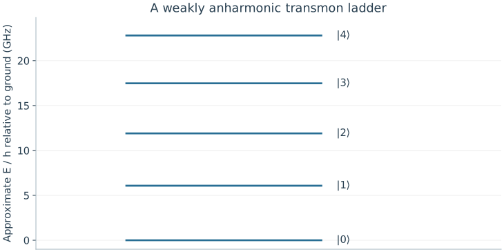
For the illustrative values \(E_C/h=0.25\) GHz and \(E_J/h=20\) GHz, \(f_{01}\simeq6.075\) GHz and \(f_{12}\simeq5.825\) GHz. By the pulse-spectrum argument, a pulse much longer than \(1/(2\pi\times0.25\,\text{GHz})\), about 0.6 ns, and much weaker than the anharmonicity distinguishes them. A stronger, shorter pulse can excite both. Initialization uses thermal relaxation or measurement-based reset. The residual excited and leaked populations must be measured, since the refrigerator temperature alone does not fix them.
8.2.2 Resonators and entangling gates
How do two circuits interact? A capacitor between them adds an energy proportional to the product of their charges. In the oscillator description each charge is proportional to \(i(a^\dagger-a)\), so the product contains \(a^\dagger b\), \(ab^\dagger\), \(ab\), and \(a^\dagger b^\dagger\), where \(b\) lowers the second circuit. Near resonance, in the rotating frame, the last two turn at the sum of the two frequencies, and the rotating-wave argument drops them. What remains is excitation exchange, \(\hbar g(a^\dagger b+ab^\dagger)\). Keeping two levels per circuit replaces \(a\) by \(\ket0\bra1\), and the coupling becomes \(\hbar g(XX+YY)/2\), the exchange interaction whose swap dynamics we already know.
Can a transmon pair also produce a conditional phase? Suppose only \(\ket{11}\) gains an extra energy \(\delta E\) for a time \(t\). Its amplitude gains \(e^{-i\delta Et/\hbar}\), and choosing that phase to be π gives a controlled sign after local phase corrections. One way to produce such a shift uses the third level. When two coupled levels are tuned toward each other, they repel instead of crossing, which is called an avoided crossing. Tuning \(\ket{11}\) close to the non-computational state \(\ket{02}\) pushes the energy of \(\ket{11}\) alone. Such a gate passes through the third level, so it must be analysed in the larger space to predict leakage, and it must end back in the qubit basis.
Quartic-approximation levels use EJ/h = 20 GHz and EC/h = 0.25 GHz. Neighboring gaps decrease by about 0.25 GHz. The plot is a low-level approximation, not an exact or measured spectrum.
Problem 8.2. Why can a shorter pulse cause leakage?
Worked solution
Its spectrum is broader and its drive amplitude is usually larger. Both make an adjacent transition harder to ignore; the relevant comparison is with the anharmonicity, not the much larger carrier frequency.
8.3 Readout and Scaling
A processor must also read its qubits, and it must keep working as it grows. How does a microwave signal learn the qubit's state, and what limits a large array? Coupling the qubit to a detuned resonator shifts the resonator's frequency by an amount that depends on the qubit's state. Residual couplings, wiring, and heat then set the cost of adding qubits.
8.3.1 Dispersive measurement
How can a qubit change a signal without being driven between its levels? Couple it to a resonator whose frequency \(\omega_r\) is far from the qubit frequency \(\omega_q\). With one excitation shared between them, the Hamiltonian is a two-by-two matrix with diagonal \(\hbar\omega_q,\hbar\omega_r\) and off-diagonal \(\hbar g\). Its eigenvalues are
For \(|g/\Delta|\ll1\), expanding the square root shifts the two uncoupled levels by about \(\pm\hbar g^2/\Delta\).
What does this do to the resonator? We quote the result of the same calculation over the whole qubit–resonator ladder, for a two-level qubit. The resonator frequency shifts by \(+\chi\) or \(-\chi\), depending on the qubit's state, with \(\chi=g^2/\Delta\). This weak-coupling, far-detuned regime is called dispersive. A probe tone near the resonator frequency therefore leaves with a phase that depends on the qubit's state, and that phase is the readout signal. A transmon's extra levels change the value of \(\chi\), and a strong probe can break the expansion. So the readout is calibrated at the actual probe power and acquisition window.
8.3.2 Materials, wiring, and crosstalk
What changes when many circuits share a chip? A small residual frequency error \(\delta\omega\) accumulates phase \(\delta\omega t\). A residual ZZ coupling between neighbours accumulates a conditional phase even during gates meant to be independent. These errors depend on time, on layout, and on which operations run together, so isolated gate measurements cannot fully predict an array.
Each added qubit also brings control lines, readout resonators, possible frequency collisions with its neighbours, and heat at the cold stages. A hypothetical installation of 1000 lines, each delivering 10 nW, already loads its stage with 10 μW before any active dissipation. This is an accounting example, not a refrigerator specification. A fabricated layout becomes a processor only when its controls can operate its usable qubits in parallel within such budgets.
Problem 8.3. If \(g/2\pi=10\) MHz and \(\Delta/2\pi=200\) MHz, what is the simple dispersive estimate?
Worked solution
\(\chi/2\pi=10^2/200=0.5\) MHz. The ratio is 0.05; multilevel effects and probe photon number still require checking.
An atom offers levels that nature makes identical from one atom to the next, but two atoms held apart in a trap do not touch. What can supply the coupling between them?
Worked model check. Use EC/h=0.2 GHz and EJ/h=15 GHz. Estimate f01 and f12 from the quartic approximation.
Worked solution
\(f_{01}\simeq\sqrt{8(15)(0.2)}-0.2\simeq4.699\) GHz, and \(f_{12}\simeq4.499\) GHz. These approximate spacings must not replace a multilevel calibration.
Josephson junctions provide a dissipationless nonlinear inductance that turns an LC microwave resonator into an anharmonic transmon, fluxonium, or phase qubit.
Transmon qubits operate at large \(E_J/E_C\) ratios to exponentially suppress charge-noise sensitivity at the cost of reduced anharmonicity (\(\alpha/2\pi \approx -200\text{ to }-300\text{ MHz}\)).
Dispersive circuit QED couples superconducting qubits to microwave transmission-line resonators for both multiplexed QND readout and bus-mediated two-qubit gates.
Questions and worked problems
These exercises draw on the whole chapter. Attempt each question before opening a hint, explain your reasoning, then compare it with the worked solution.
An LC resonator has \(L=10\) nH and \(C=100\) fF. Find its frequency \(f=1/(2\pi\sqrt{LC})\). Why can it not serve as a qubit by itself?
Hint 1
\(LC=10^{-21}\ \mathrm{s^2}\).
Hint 2
Its quantized levels are equally spaced.
Worked solution
\(\sqrt{LC}=3.16\times10^{-11}\) s, so \(f\approx5.0\) GHz. Its quantized levels are equally spaced, \(\hbar\omega(n+\frac12)\), so a drive resonant with \(0\to1\) is also resonant with \(1\to2\) and every higher transition. Without nonlinearity no frequency selects a two-level subspace; the Josephson junction supplies that nonlinearity.
A transmon has \(E_J/h=16\) GHz and \(E_C/h=0.25\) GHz. Estimate \(f_{01}\), \(f_{12}\), and the anharmonicity from \(\hbar\omega_{01}\simeq\sqrt{8E_JE_C}-E_C\). Is \(E_J/E_C\) in the transmon regime?
\(\sqrt{8E_JE_C}/h\approx5.66\) GHz, so \(f_{01}\approx5.41\) GHz, \(f_{12}\approx5.16\) GHz, and the anharmonicity is about \(-250\) MHz. \(E_J/E_C=64\), well inside the regime where the quartic expansion is a reasonable approximation and charge sensitivity is strongly suppressed.
A transmon is coupled to a readout resonator with \(g/2\pi=50\) MHz and detuning \(\Delta/2\pi=1\) GHz. Estimate the dispersive shift scale \(\chi=g^2/\Delta\), and check the condition for the approximation.
Hint 1
\(\chi/2\pi=(50\ \text{MHz})^2/(1\ \text{GHz})\).
Hint 2
The expansion requires \(|g/\Delta|\ll1\).
Worked solution
\(\chi/2\pi=2500/1000=2.5\) MHz. The ratio \(g/\Delta=0.05\) is small, so the two-level dispersive expansion is reasonable here (the transmon’s higher levels modify the exact value). A shift of a few megahertz, compared with a resonator linewidth of similar size, lets a probe tone acquire a clearly different phase for the two qubit states.
Verify the transmon spectrum from the quartic correction \(-E_C(6n^2+6n+3)/12\). (a) Evaluate it for \(n=0,1,2\). (b) Add the harmonic part \(\sqrt{8E_JE_C}(n+\frac12)\) and compute \(E_1-E_0\) and \(E_2-E_1\). (c) Show that the anharmonicity is \(-E_C\), and evaluate everything for \(E_J/h=20\) GHz, \(E_C/h=0.25\) GHz.
Hint 1
The corrections are \(-\frac14E_C\), \(-\frac{15}{12}E_C\), \(-\frac{39}{12}E_C\).
(a) \(n=0\): \(-0.25E_C\); \(n=1\): \(-1.25E_C\); \(n=2\): \(-3.25E_C\). (b) \(E_1-E_0=\sqrt{8E_JE_C}-E_C\) and \(E_2-E_1=\sqrt{8E_JE_C}-2E_C\). (c) Their difference is \(-E_C\). With the given values, \(\sqrt{8E_JE_C}/h\approx6.325\) GHz, so \(f_{01}\approx6.075\) GHz, \(f_{12}\approx5.825\) GHz, and the anharmonicity is \(-250\) MHz, as quoted for the illustrative transmon. The level spacing shrinks by \(E_C\) at each step because the cosine potential is softer than a parabola.
For a qubit-resonator pair with \(g/2\pi=100\) MHz and \(\Delta/2\pi=500\) MHz, (a) compute the exact level shift \(\sqrt{\Delta^2/4+g^2}-\Delta/2\) and compare it with the dispersive estimate \(g^2/\Delta\). (b) Repeat for \(\Delta/2\pi=200\) MHz. (c) What goes wrong as \(g/\Delta\) grows?
Hint 1
Work in MHz: \(\sqrt{250^2+100^2}-250\).
Hint 2
For \(\Delta=200\): \(\sqrt{100^2+100^2}-100\).
Worked solution
(a) Exact: \(\sqrt{62500+10000}-250\approx19.3\) MHz; dispersive: \(20\) MHz, about \(4\%\) too large. (b) Exact: \(\sqrt{20000}-100\approx41.4\) MHz; dispersive: \(50\) MHz, \(21\%\) too large. (c) At \(g/\Delta=0.5\) the eigenstates are strongly mixed qubit-resonator states, so “qubit state” and “resonator photon” are no longer separate, the readout photons can drive qubit transitions, and the qubit inherits the resonator’s loss. The dispersive regime trades signal size for clean, nondemolition readout.
A two-qubit gate gives the state \(\ket{11}\) an extra energy \(\delta E/h=2\) MHz. (a) How long must it act to give a controlled phase \(\pi\)? (b) When the gate is off, a residual \(ZZ\) shift of \(\zeta/2\pi=100\) kHz remains. What conditional phase builds up during \(1\) μs of idling? (c) How does this affect \(\ket{++}\)?
Hint 1
Phase \(=2\pi\times(\delta E/h)\times t\).
Hint 2
A conditional phase \(\phi\) changes \(\ket{++}\) to \(\frac12(\ket{00}+\ket{01}+\ket{10}+e^{-i\phi}\ket{11})\).
Worked solution
(a) \(2\pi\times2\ \text{MHz}\times t=\pi\) gives \(t=250\) ns. (b) \(2\pi\times0.1\ \text{MHz}\times1\ \mu\mathrm s\approx0.63\) rad of unwanted conditional phase, a fifth of a controlled-\(Z\). (c) The idle state \(\ket{++}\) becomes partly entangled, with \(|\alpha_{00}\alpha_{11}-\alpha_{01}\alpha_{10}|=\frac14|e^{-i\phi}-1|\approx0.15\). Residual always-on coupling turns idle time into an error that depends on the neighbors’ states, so it must be suppressed, echoed away, or included in the schedule.
Estimate cryogenic wiring loads: each control line deposits \(10\) nW at a cold stage. (a) A \(100\)-qubit processor uses \(3\) lines per qubit. What is the load? (b) A \(5000\)-qubit processor with the same wiring? (c) If the stage can absorb \(20\) μW, how many qubits fit, and what design changes would raise the limit?
(a) \(300\) lines give \(3\) μW. (b) \(15000\) lines give \(150\) μW. (c) At \(30\) nW per qubit, \(20\) μW supports about \(670\) qubits, before counting active dissipation in amplifiers or the heat conducted by the cables themselves. Raising the limit requires fewer lines per qubit (multiplexed readout, shared control), lower-loss lines, or control electronics placed at warmer stages or made cryogenic. These figures are illustrative, but the scaling is real: wiring grows with qubit count.
A student argues: “Increasing the qubit-resonator coupling \(g\) always improves readout, because \(\chi=g^2/\Delta\) grows.” Using the exact shifts from the worked problem above, explain why this is not true, and name two costs of large \(g/\Delta\).
Hint 1
At \(g/\Delta=0.5\), the dispersive formula is \(21\%\) off.
Hint 2
The qubit inherits loss from the resonator.
Worked solution
At small \(g/\Delta\), \(\chi\) does grow as \(g^2/\Delta\), but by \(g/\Delta=0.5\) the dispersive formula is far off and the qubit and resonator are strongly hybridized. Costs include the qubit decaying through the resonator (Purcell decay), measurement photons inducing qubit transitions, and a stronger dependence of \(\chi\) on probe power. Good readout needs \(\chi\) comparable to the resonator linewidth while staying in the dispersive regime, often with filters to block Purcell decay.
Two coupled transmons can suffer a frequency collision when an unwanted transition of one is resonant with a transition of the other. Qubit A has \(f_{01}=5.00\) GHz and \(f_{12}=4.70\) GHz; qubit B has \(f_{01}=4.70\) GHz. (a) Which process becomes resonant, and why is it harmful? (b) Propose a frequency for B that avoids collisions with A’s \(f_{01}\) and \(f_{12}\) by at least \(100\) MHz while staying within \(0.5\) GHz of A. (c) Why does this make large arrays hard to lay out?
Hint 1
Compare B’s \(f_{01}\) with A’s \(f_{12}\).
Hint 2
Exchange can swap an excitation between A’s \(1\to2\) and B’s \(0\to1\).
Worked solution
(a) B’s \(0\to1\) is resonant with A’s \(1\to2\). Through exchange, the state \(\ket{1_A1_B}\) can turn into \(\ket{2_A0_B}\), leaking A out of the qubit subspace during any operation that populates \(\ket{11}\). (b) B must avoid \(5.00\pm0.10\) and \(4.70\pm0.10\) GHz; choosing \(f_{01}^B=4.85\) GHz works, \(150\) MHz from both. (c) Each qubit must avoid collisions with every neighbor’s transitions, and fabrication scatter in junction energies shifts frequencies by tens of megahertz, so many fixed-frequency qubits quickly run out of safe frequency space. This motivates tunable couplers, careful frequency allocation, and post-fabrication trimming.
A qubit coupled to a readout resonator can decay through it at the Purcell rate \(\Gamma_P\approx\kappa(g/\Delta)^2\), where \(\kappa\) is the resonator’s energy decay rate. (a) For \(\kappa/2\pi=5\) MHz and \(g/\Delta=0.05\), find \(\Gamma_P/2\pi\) and the corresponding \(T_1\) limit. (b) How does increasing \(\kappa\) for faster readout affect it? (c) What is the role of a Purcell filter?
Hint 1
\(\Gamma_P/2\pi=5\ \text{MHz}\times0.0025\).
Hint 2
\(T_1=1/\Gamma_P\).
Worked solution
(a) \(\Gamma_P/2\pi=12.5\) kHz, so \(T_1\le1/(2\pi\times12.5\ \text{kHz})\approx13\) μs, a severe limit for a modern qubit. (b) Readout speed grows with \(\kappa\), but so does Purcell decay, linearly: faster readout costs coherence. (c) A Purcell filter passes signals near the resonator frequency to the amplifier while blocking emission at the qubit frequency, breaking this trade-off so that \(\kappa\) can be large without shortening \(T_1\).