Starting point: Earlier programming chapters; relevant constructions from Quantum Computing and Quantum Algorithms.
Anchor example: Construct and verify a reversible predicate and its phase-oracle form.
This lesson includes explanations, worked examples, and problems with solutions. Advanced results whose proofs are outside the chapter are identified explicitly.
In the algorithms course, an oracle was a given: a unitary \(U_f\ket x\ket y=\ket x\ket{y\oplus f(x)}\) that some earlier stage supplied. We could count how many times an algorithm called it, without asking what it was made of. Our programs cannot take that shortcut. Every gate an oracle contains has to be written, and it has to be correct on superpositions, since that is how algorithms use it.
So how do we implement an oracle rather than assume it exists? We build one for a small function and check its complete contract, including what it does to a target that starts in 1. Oracles that compute arithmetic bring two new requirements, a fixed bit width and workspace that must be cleaned. Finally, most algorithms want the function’s value as a sign on each amplitude, so we turn the bit oracle into a phase oracle, test those signs coherently, and count what the oracle costs.
The function \(f(a,b,c)=ab\oplus c\) carries us through. It is small enough to check exhaustively, and rich enough to separate a truth table from a coherent circuit.
7.1 Reversible Predicates
Our predicate takes three bits and returns one. To evaluate it with unitary gates, we cannot simply replace the inputs with the output, because that would discard information. Instead we keep the inputs and add the answer to a fourth qubit. We first choose the gates, then state and test the contract for every value of that fourth qubit.
7.1.1 Boolean evaluation
Which gates add \(ab\oplus c\) to a target qubit? We place \(a,b,c\) on qubits 0, 1 and 2 and the target on qubit 3. The function is an XOR of two terms, and flipping a bit twice is the same as flipping it by the XOR of the two reasons. So we can handle each term with its own gate.
The term \(ab\) is an AND, and a Toffoli controlled by qubits 0 and 1 flips the target exactly when \(ab=1\). The term \(c\) needs a CNOT from qubit 2. Together they send the target \(t\) to \(t\oplus ab\oplus c\) and leave the inputs untouched. This predicate needs no ancilla.
A larger predicate would. For \((a\wedge b)\wedge(c\vee d)\), say, the intermediate values need ancillas, and we use the pattern we met for the three-input AND. We compute the intermediate values into clean ancillas, copy the final value into the target with a CNOT, and then reverse the computing gates so the ancillas return to \(\ket0\). This pattern is called compute–copy–uncompute.
7.1.2 Answer registers and retained inputs
Suppose we test the circuit on the eight inputs with target 0, and the target always ends as \(f\). Is the oracle correct? Not necessarily. A circuit that first resets the target and then computes \(f\) passes every one of those tests. On target 1, though, it returns \(f\) instead of \(1\oplus f\), and since it contains a reset it is not even unitary. The answer operation of an oracle is XOR, not assignment, so the contract must hold for target 0 and target 1.
So we check all \(2^4=16\) basis inputs. Column \(k\) of the circuit’s matrix is its output for basis input \(k\), and the expected output is the same basis state with the target bit flipped when \(f=1\). How does a program compute that? An integer from 0 to 15 holds the four qubit values as its binary digits, with qubit 0 as the least significant digit, exactly as in our bit-order convention. Python’s bitwise operators act on those digits. To read qubit \(k\), we shift the digits right by \(k\) places with index >> k, which drops the lowest \(k\) digits. Then & 1 keeps only the lowest remaining digit, so (index >> k) & 1 is the value of qubit \(k\). To write the target, we need the opposite shift: f << 3 moves \(f\) to digit 3, giving 8 when \(f=1\) and 0 otherwise. Finally ^ is XOR applied digit by digit.
So index ^ (f << 3) flips the target’s digit exactly when \(f=1\). In the companion, for index in range(16): repeats its indented body for each index from 0 to 15. The line a, b, c = … assigns three names at once from three values. matrix[:, index] selects column index, where the colon means “all rows,” and np.eye(16)[:, expected] is the basis vector we expect.
Why compare whole columns rather than probabilities? A linear operator is fixed by what it does to the basis states, including the phases of the outputs. An extra Z on one qubit changes no basis probability, yet it changes the column’s sign, and the column test catches it.
Problem 7.1. What happens to an answer target initially one when f=1?
Worked solution
It becomes zero. The answer operation is XOR, not assignment.
7.2 Arithmetic Circuits
Our predicate used only AND and XOR. Algorithms often need oracles that do arithmetic, adding or comparing integers stored in qubits. An integer on qubits has a fixed number of digits, and arithmetic usually needs intermediate values. So we must decide what happens when a result does not fit, and where the intermediate values live. We start with addition and comparison, then turn to width and workspace.
7.2.1 Addition and comparison
How do we add 1 to a two-bit number \(x=x_0+2x_1\) with reversible gates? In ordinary binary addition the low digit always flips, and the high digit flips exactly when the low digit was 1, because that produces a carry. The order of gates matters: the carry depends on the low digit’s old value. So we first apply a CNOT from qubit 0 to qubit 1, and only then an X on qubit 0. Checking the four inputs: \(0\to1\), \(1\to2\), \(2\to3\), and \(3\to0\).
The last case shows that the circuit computes addition modulo 4. It has to: it is a permutation of four basis states, so it cannot produce a fifth. If we want to keep the overflow, we must add a qubit for it. Either choice is legitimate, but the program must make it explicitly. The bit width is part of the function.
Comparison follows the compute–copy–uncompute pattern. To decide whether \(a<b\), we compute \(a-b\) and look at whether the subtraction needs a borrow from beyond the top digit. We copy that borrow flag into the target, then reverse the subtraction to restore the workspace.
7.2.2 Precision and workspace requirements
What if the numbers are not integers? A common choice is fixed point: store an integer \(m\) and read it as \(m/2^k\). With 4 bits and \(k=2\), the representable values are \(0,0.25,0.5,\dots,3.75\). Adding a bit can extend the range or refine the spacing, so changing the width changes both range and precision.
Arithmetic also needs space. Carries, comparison flags and partial products each need wires, and each must be uncomputed. If we report only the final gate that writes the answer, we hide most of the oracle’s cost. The same holds when an oracle looks up values in a finite table. Loading the table, or reading from it, needs a circuit of its own, with its own cost.
Problem 7.2. Is a four-bit adder an implementation of arbitrary-precision integer addition?
Worked solution
No. Its range and overflow behavior are fixed. A scalable implementation specifies a family parameterized by width and gives its resource growth.
7.3 Phase Oracles
Search and many other algorithms do not want \(f(x)\) written in a target. They want each input’s amplitude multiplied by \((-1)^{f(x)}\). Can our bit oracle provide that sign without a new circuit? If it can, we must test the signs, and a histogram cannot see a sign. We derive the phase form first, then test it and count its cost.
7.3.1 Compute, phase, and uncompute
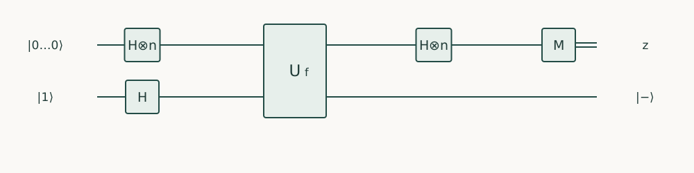
Suppose the target starts in \(\ket-=(\ket0-\ket1)/\sqrt2\) instead of a basis state. The bit oracle sends \(\ket x\ket0\) to \(\ket x\ket{f(x)}\) and \(\ket x\ket1\) to \(\ket x\ket{1\oplus f(x)}\), so \[U_f\ket x\ket-=\ket x\,\frac{\ket{f(x)}-\ket{1\oplus f(x)}}{\sqrt2}=(-1)^{f(x)}\ket x\ket-.\] When \(f(x)=0\) nothing changes, and when \(f(x)=1\) the two terms swap, which flips the sign. The target is unchanged, and the sign has moved onto the input. This is called phase kickback, and \(U_f\) used this way is a phase oracle.
In a larger predicate, the ancillas must be uncomputed before this works. A retained ancilla would carry \(f\)-dependent values, and the input state would not factor away from the workspace.
To test it, the companion prepares all eight inputs with equal amplitude, using H on qubits 0, 1 and 2. It prepares \(\ket-\) on the target with X and then H. Each input amplitude is \(1/\sqrt8\) and each target amplitude is \(\pm1/\sqrt2\), so after the oracle the amplitude of basis index \(k\) should be \[\frac{(-1)^{f(a,b,c)\oplus t}}{4},\] where \(t\) is the target bit of \(k\). The code builds this list of 16 numbers. The expression [(index >> k) & 1 for k in range(4)] is a list comprehension: it makes a list from the expression before for, evaluated at each \(k\). Here it gives the four bits of index. Starting from the empty list [], the method append adds one expected amplitude per index.
7.3.2 Superposition tests and resource counts
Why insist on comparing amplitudes? In this state every one of the 16 amplitudes has magnitude \(1/4\). So every basis probability is \(1/16\), whatever \(f\) is. A histogram of measured counts would look the same for the correct oracle, for a wrong one, and for no oracle at all. Only the signs carry \(f\), and the companion compares all 16 complex amplitudes at once. That one test checks every sign and also checks that the target ends in \(\ket-\), unentangled from the inputs.
What does the oracle cost? Logically, one Toffoli and one CNOT, plus the preparation and any readout. A Toffoli is not native on most devices. Compiled to CNOTs and one-qubit gates, it takes 6 CNOTs. So a resource report should give both the logical count and the compiled count. Because its contract is simple, inputs kept and target XORed, the oracle can serve as a component in search, in phase encoding, or in a larger arithmetic circuit.
"""Runnable companion for Quantum Programming, Chapter 7."""
import numpy as np
from qiskit import QuantumCircuit
from qiskit.quantum_info import Operator, Statevector

# f(a,b,c) = ab XOR c; q0=a, q1=b, q2=c, q3=target.
qc = QuantumCircuit(4)
qc.ccx(0, 1, 3)
qc.cx(2, 3)
matrix = Operator(qc).data
for index in range(16):
    a, b, c = index & 1, (index >> 1) & 1, (index >> 2) & 1
    expected = index ^ (((a & b) ^ c) << 3)
    assert np.allclose(matrix[:, index], np.eye(16)[:, expected])
# Target minus makes the same oracle a phase oracle.
prep = QuantumCircuit(4)
prep.h([0, 1, 2])
prep.x(3)
prep.h(3)
state = Statevector.from_instruction(prep.compose(qc))
expected = []
for index in range(16):
    a, b, c, target = [(index >> k) & 1 for k in range(4)]
    expected.append((-1)**((a & b) ^ c ^ target) / 4)
assert np.allclose(state.data, expected)
print("All basis columns and coherent signs verified")
It turns function values into relative phases and exposes phase or cleanup errors that may be invisible on measured basis inputs.
Phase-oracle readout. U_f is the reversible bit oracle on the input register and the minus target, not an elementary gate. The final input measurement reads the encoded pattern.
With an oracle we can build and verify, the algorithms we studied abstractly become possible to program. What does each of them add to the code beyond its oracle?
A concrete oracle is not a magic black box; it is a reversible Boolean or arithmetic circuit synthesized from classical logic gates without leaking path information into uncleaned ancillas.
Bit-flip oracles \(|x,y\rangle \mapsto |x, y\oplus f(x)\rangle\) convert into phase oracles \((-1)^{f(x)}|x\rangle\) either by targeting a \(|-\rangle\) ancilla or by direct multi-controlled phase synthesis.
Reversible adders, comparators, and modular multipliers dominate the gate count of practical Grover and Shor implementations.
Questions and worked problems
These exercises draw on the whole chapter. Attempt each question before opening a hint, explain your reasoning, then compare it with the worked solution.
For the oracle \(f(a,b,c)=ab\oplus c\) (qubits 0, 1, 2 hold \(a,b,c\); qubit 3 is the target), which basis state does the input \(a=b=c=1\) with target \(0\) map to? Give its index.
Hint 1
\(f(1,1,1)=1\oplus1\).
Hint 2
Index \(=a+2b+4c+8t\).
Worked solution
\(f(1,1,1)=1\oplus1=0\), so the target stays \(0\) and the state is unchanged: index \(7\) maps to index \(7\). The Toffoli and the CNOT each flip the target, and the two flips cancel. Exhaustive checks over all sixteen columns catch mistakes in exactly these cancelling cases.
The two-bit incrementer applies cx(0, 1) and then x(0). Tabulate its action on the four inputs \(0,1,2,3\). What happens to \(3\), and why does that keep the circuit reversible?
Hint 1
The CNOT flips the high bit when the low bit is \(1\).
Hint 2
Arithmetic modulo \(4\).
Worked solution
\(0\to1\), \(1\to2\), \(2\to3\), and \(3\to0\). The overflow wraps around: this is addition modulo \(4\), a permutation of the four labels, and therefore reversible. Producing \(4\) would need a third bit; the width is part of the function’s definition.
from qiskit import QuantumCircuit
from qiskit.quantum_info import Statevector

def increment():
    circuit = QuantumCircuit(2)
    circuit.cx(0, 1)
    circuit.x(0)
    return circuit

for value in range(4):
    circuit = QuantumCircuit(2)
    for qubit in range(2):
        if value >> qubit & 1:
            circuit.x(qubit)
    circuit.compose(increment(), inplace=True)
    probabilities = Statevector.from_instruction(circuit).probabilities_dict()
    assert int(max(probabilities, key=probabilities.get), 2) == (value + 1) % 4
The oracle uses one Toffoli and one CNOT. Transpile it to the basis cx, rz, sx, x with all-to-all connectivity, and then on a line of four qubits. Report the CNOT counts.
Hint 1
A Toffoli needs six CNOTs in this basis.
Hint 2
A line forces routing for non-adjacent qubits.
Worked solution
With all-to-all connectivity the compiled oracle has \(7\) CNOTs (six for the Toffoli, one for the CNOT). On a line it needs more, about \(10\) in this run, because qubits 0, 1, and 3 are not all adjacent and swaps are inserted. Report both the logical count and the compiled count for a stated target.
from qiskit import QuantumCircuit, transpile
from qiskit.transpiler import CouplingMap

oracle = QuantumCircuit(4)
oracle.ccx(0, 1, 3)
oracle.cx(2, 3)
basis = ["cx", "rz", "sx", "x"]
full = transpile(oracle, basis_gates=basis, optimization_level=1)
line = transpile(oracle, basis_gates=basis, coupling_map=CouplingMap.from_line(4), optimization_level=1, seed_transpiler=1)
assert full.count_ops()["cx"] == 7 and line.count_ops()["cx"] > 7
A buggy oracle appends cz(3, 0) after the correct gates. (a) Show that its output probabilities match the correct oracle on every basis input. (b) Show that the full operator comparison fails. (c) What kind of error does this represent, and which test in the chapter catches it?
Hint 1
A CZ only multiplies some basis states by \(-1\).
Hint 2
Compare probabilities column by column, then compare operators.
Worked solution
(a) CZ changes only signs, so every basis input produces the same output label with the same probability as the correct oracle. (b) The operators differ: the bug multiplies outputs with \(a=1\) and target \(1\) by \(-1\). (c) It is a phase error. When the oracle is used coherently, as in a phase-kickback algorithm, it corrupts interference. The chapter’s coherent sign test on a uniform superposition with target \(\ket-\), and the full column comparison including phases, both catch it; histograms do not.
import numpy as np
from qiskit import QuantumCircuit
from qiskit.quantum_info import Operator

good = QuantumCircuit(4)
good.ccx(0, 1, 3)
good.cx(2, 3)
bad = good.copy()
bad.cz(3, 0)
g, b = Operator(good).data, Operator(bad).data
assert all(np.allclose(np.abs(g[:, i]) ** 2, np.abs(b[:, i]) ** 2) for i in range(16))
assert not Operator(good).equiv(Operator(bad))
Build a two-bit equality test: qubits 0, 1 hold \(a\), qubits 2, 3 hold \(b\), and qubit 4 receives \([a=b]\), with \(b\) restored. Use CNOTs to compute \(a\oplus b\) into \(b\), X gates and a Toffoli to set the flag when both XOR bits are \(0\), and then uncompute. Verify all \(16\) inputs.
Hint 1
After cx(0, 2) and cx(1, 3), qubits 2, 3 hold \(a_0\oplus b_0\) and \(a_1\oplus b_1\).
Hint 2
Flip them with X so that the Toffoli fires when both XORs are \(0\).
Worked solution
Compute \(a\oplus b\) into qubits 2 and 3 with two CNOTs, flip both with X, and apply a Toffoli from qubits 2, 3 to the flag, which fires exactly when both XOR bits were \(0\). Then undo the X gates and the CNOTs in reverse order, restoring \(b\). The check below confirms that every input maps to itself with the correct flag. The comparison reuses \(b\) as workspace instead of a separate scratch register, at the cost of a careful uncompute.
from itertools import product
from qiskit import QuantumCircuit
from qiskit.quantum_info import Statevector

def equal_2bit():
    circuit = QuantumCircuit(5)
    circuit.cx(0, 2)
    circuit.cx(1, 3)
    circuit.x([2, 3])
    circuit.ccx(2, 3, 4)
    circuit.x([2, 3])
    circuit.cx(1, 3)
    circuit.cx(0, 2)
    return circuit

for a0, a1, b0, b1 in product([0, 1], repeat=4):
    circuit = QuantumCircuit(5)
    for qubit, value in enumerate([a0, a1, b0, b1]):
        if value:
            circuit.x(qubit)
    circuit.compose(equal_2bit(), inplace=True)
    probabilities = Statevector.from_instruction(circuit).probabilities_dict()
    flag = int(a0 == b0 and a1 == b1)
    assert probabilities[f"{flag}{b1}{b0}{a1}{a0}"] > 0.999
For \(f(a,b,c)=ab\oplus c\), the phase \((-1)^{f}\) factors as \((-1)^{ab}(-1)^{c}\). (a) Implement the phase oracle with cz(0, 1) and z(2), using no target qubit. (b) Verify that, on the uniform input with the target in \(\ket-\), it produces the same state as the bit oracle. (c) What does this save?
Hint 1
CZ applies \((-1)^{ab}\); Z applies \((-1)^{c}\).
Hint 2
Compare statevectors on the same prepared input.
Worked solution
(a) cz(0, 1) multiplies by \((-1)^{ab}\) and z(2) by \((-1)^c\), together \((-1)^{f}\). (b) Applying them to the uniform input, with the unused target prepared in \(\ket-\), gives the same state as the bit oracle with target \(\ket-\). (c) It removes the Toffoli entirely (six CNOTs after compilation) and the target qubit. When a function is an XOR of simple terms, writing the phase directly is far cheaper than computing the bit and kicking it back.
An oracle must apply the phase \(e^{2\pi i\,0.3}\) using a fixed-point register. (a) With \(3\) fractional bits, which representable value is closest to \(0.3\), and what is the phase error? (b) Repeat with \(5\) bits. (c) How many bits keep the phase error below \(10^{-3}\) rad?
Hint 1
Representable values are multiples of \(2^{-m}\).
Hint 2
Phase error \(=2\pi\times\)(value error).
Worked solution
(a) \(0.3\times8=2.4\), so the nearest value is \(2/8=0.25\), an error of \(0.05\) and a phase error of \(0.31\) rad. (b) \(0.3\times32=9.6\), nearest \(10/32=0.3125\): error \(0.0125\), phase error \(0.079\) rad. (c) Rounding error is at most \(2^{-m-1}\), so the phase error is at most \(\pi2^{-m}\); requiring \(\le10^{-3}\) gives \(m\ge12\). Each bit halves the error but adds a wire and its arithmetic.
A student uses the two-bit incrementer to compute \(3+1\) and reports a bug when the output is \(0\). Is it a bug? What should the program have specified, and how would you obtain \(4\)?
Hint 1
The incrementer is defined modulo \(4\).
Hint 2
Representing \(4\) needs three bits.
Worked solution
It is not a bug in the circuit: the two-bit incrementer computes \(x+1\bmod4\), and \(3+1\equiv0\). The bug is a mismatch between the specification and the intended use. To obtain \(4\), use a three-bit register (and a three-bit incrementer) or an explicit carry output; every arithmetic component must state its width and its overflow behavior.
Build a three-bit incrementer using a multi-controlled X: first flip bit 2 if bits 0 and 1 are both \(1\), then flip bit 1 if bit 0 is \(1\), then flip bit 0. Verify it on all eight inputs, and explain why the order must go from the high bit down.
Hint 1
Use mcx([0, 1], 2), then cx(0, 1), then x(0).
Hint 2
Each conditional flip reads lower bits before they change.
Worked solution
Each bit should flip exactly when all lower bits are \(1\) in the original input. Processing from the high bit down ensures every controlled flip reads the lower bits before they are modified; the reverse order would read already-incremented bits. The check confirms \(v\to v+1\bmod8\) for all inputs. Larger widths need multi-controlled X gates with many controls, whose decomposition cost grows with \(n\).
from qiskit import QuantumCircuit
from qiskit.quantum_info import Statevector

def increment3():
    circuit = QuantumCircuit(3)
    circuit.mcx([0, 1], 2)
    circuit.cx(0, 1)
    circuit.x(0)
    return circuit

for value in range(8):
    circuit = QuantumCircuit(3)
    for qubit in range(3):
        if value >> qubit & 1:
            circuit.x(qubit)
    circuit.compose(increment3(), inplace=True)
    probabilities = Statevector.from_instruction(circuit).probabilities_dict()
    assert int(max(probabilities, key=probabilities.get), 2) == (value + 1) % 8
An oracle is specified only by its truth table on \(n\) inputs. (a) How many basis columns must an exhaustive operator check compare, including both target values? (b) For which \(n\) does a dense Operator check become impractical? (c) What alternative checks scale better, and what do they give up?
Hint 1
Inputs times target values: \(2^{n+1}\) columns.
Hint 2
Each column has \(2^{n+1}\) entries.
Worked solution
(a) \(2^{n+1}\) columns (all inputs, both target values), each of length \(2^{n+1}\). (b) Around \(n=12\) to \(14\), the dense matrix has \(4^{n+1}\) entries, hundreds of millions to billions, too large for routine testing. (c) Check each basis input with a statevector or a classical reversible simulation (\(2^{n+1}\) runs, each cheap), plus a few coherent superposition tests for phases; or verify the construction compositionally, component by component. These scale further but no longer examine every matrix entry at once, so phase checks must be designed deliberately.